Language


Views: 218 Author: Yinda Powder Coating Publish Time: 2026-11-19 Origin: Site


Content Menu
● What Powder Coating Thickness Should You Specify for Aluminum Profiles?
● Why Powder Coating Builds Unevenly on Aluminum Extrusions
>> The Faraday Cage Effect Leaves Recesses Thin
>> Poor Grounding and Unstable Feed Create Different Thickness Patterns
● How to Measure Powder Coating Film Thickness on Aluminum Profiles
>> Verify the Gauge on Representative Geometry
>> Build a Thickness Map Across the Section and Along the Length
● How to Reduce Thickness Variation on the Powder Coating Line
● Worked Example: A Passing Average That Hides a Thin Groove
● What to Check When the Film Is Thick Enough but Still Looks Uneven
● Plan Your Next Aluminum Profile Coating Trial with Yinda Technology
>> Is 60 µm enough for powder coating on aluminum profiles?
>> How do you measure powder coating thickness on aluminum without damaging it?
>> Why is the outside face thick while the inside corner is thin?
>> Can thicker powder coating compensate for poor pretreatment?
>> Can a flat test panel replace measurements on an extrusion?
>> Does the film thickness gauge tell you whether the powder is fully cured?
To control powder coating film thickness on aluminum profiles, measure the areas most likely to be thin—not just the flat face that is easiest to reach. Recesses, gasket grooves, and inside corners can remain below specification while exposed shoulders build up too much powder. Set an acceptance range for the selected coating, map the critical surfaces, and verify the cured film at those locations. If the flats are already thick and the channel is thin, adjust how powder enters the channel before increasing overall output.

Dry film thickness (DFT) is the thickness of the coating after curing. It is usually reported in micrometers (µm) or mils, where 1 mil equals 25.4 µm. The right specification depends on the coating system, the service environment, the profile geometry, and the surfaces that must be protected or fit together.
For architectural aluminum, QUALICOAT specifies a 60 µm minimum for single-coat Class 1, Class 1.5, and Class 2 powders. The minimum differs for other systems, so 60 µm is not a universal target. Nor should a buyer interpret that minimum as an instruction to set the production line to exactly 60 µm. The line needs enough operating margin to accommodate normal variation without exceeding the upper limit established for the product or application.
Before approving a sample, put three items on the drawing or inspection plan:
- Identify the significant surfaces: the faces, returns, grooves, or other areas to which the agreed appearance or performance requirements apply.
- State the minimum and any applicable maximum, along with the rule for evaluating individual readings, measurement areas, and averages.
- Mark masking and fit-critical locations, such as gasket seats, sliding tracks, electrical contacts, and mating surfaces.
A window frame and an enclosure rail may use the same powder but need different inspection locations. The window frame might prioritize a weather-facing return; the rail might need an upper thickness limit in a slot so the mating part still fits.
In electrostatic powder coating, charged particles are attracted to a grounded workpiece. At a deep or narrow recess, the electric field tends to concentrate around the opening and exposed shoulders. Powder deposits there more readily than at the back of the channel. This is the Faraday cage effect. The typical clue is a heavy film at the lips and a thin film deeper inside.
Turning up the voltage can make that contrast worse. Instead, test a lower-voltage or current-limited setting supported by the equipment, give the spray a clearer path into the recess, and trial a recess-first pass. Check the cured thickness at both the shoulder and the channel floor before keeping the change.
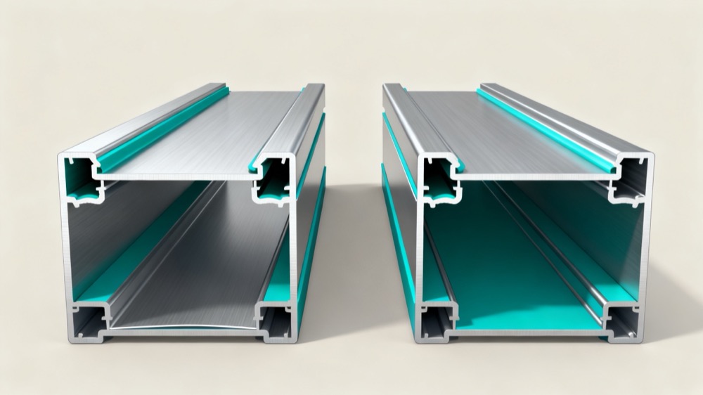
Powder buildup on hooks and contact points can interrupt the electrical path between the profile and ground. If identical profiles vary by hanger position, inspect the contact points and verify the ground path according to the equipment manufacturer's procedure before changing the spray program.
When light and heavy bands repeat along the extrusion, check whether the pattern corresponds to gun movement, conveyor speed, or changes in powder delivery. If the problem starts after a color change or a change in reclaim ratio, compare feed stability and film build against the last accepted run. The pattern tells you where to investigate; it does not prove the cause.
| Cured-film pattern | What to check first | How to verify the correction |
|---|---|---|
| Thick shoulders, thin channel floor | Profile orientation, gun angle, electrostatic settings | Measure both shoulders and the channel floor |
| One side consistently thinner | Rack shadowing, gun alignment, part spacing | Compare corresponding points on both sides |
| Identical profiles differ by hanger | Hook contact and grounding continuity | Compare profiles at different rack positions |
| Bands repeat along the extrusion | Gun travel, conveyor speed, and powder feed | Repeat measurements along the length |
| Gauge readings jump near a narrow lip | Probe seating and distance from the edge | Repeat at a marked, validated location |
Use an eddy-current coating thickness gauge suitable for nonconductive coatings on aluminum. ISO 2360 describes the amplitude-sensitive eddy-current method. A magnetic-only gauge intended for steel is not the right instrument for this substrate.
Before taking production readings, follow the instrument manufacturer's verification and adjustment procedure. Where possible, use an uncoated sample of the same extrusion and suitable thickness standards. A probe that reads correctly on a flat reference can still give misleading results near an edge or on a narrow radius. Make sure it seats consistently at each marked location.
If the probe cannot reach the bottom of a groove, do not record the adjacent shoulder as its substitute. Agree on a suitable small-footprint probe, a validated measurement location, or a sectioned trial sample before production. Otherwise, a passing report may provide no evidence about the surface that matters most.
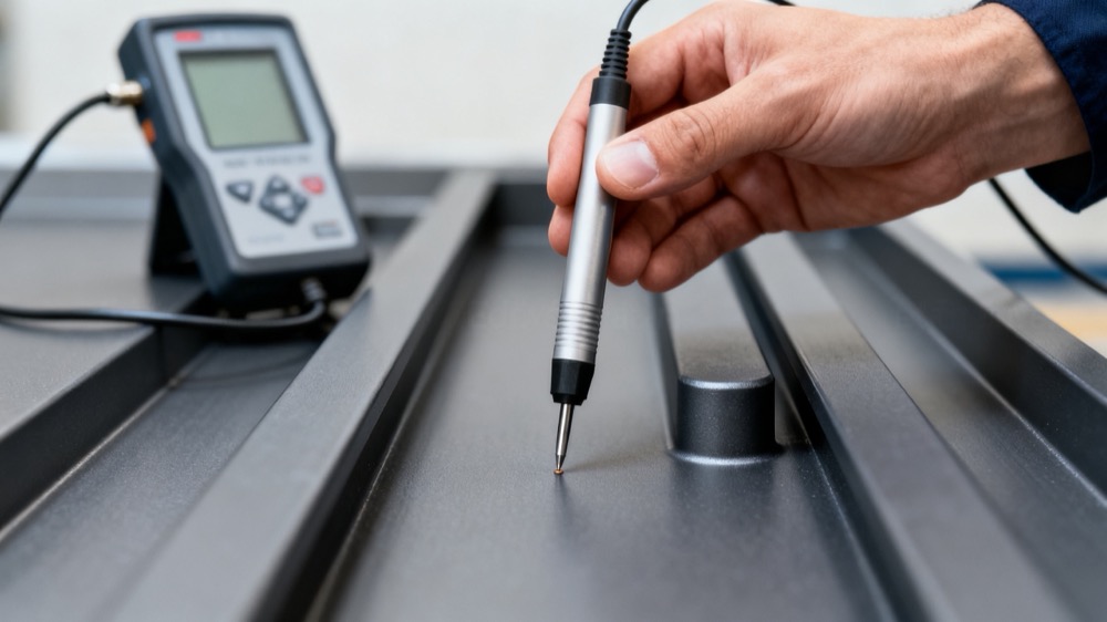
Use a marked cross-section to identify the exposed face, the left and right shoulders, the inner return, and any recess floor that requires coverage. Then take readings at defined positions along the profile. For a first-off trial, a practical starting layout is near both ends and at mid-length, with the exact locations chosen to avoid unintended edge effects and to reflect how the profile is racked.
Record results by location rather than reporting only a part-wide average. A location-based record shows whether a process change improved the recess or simply added powder to the faces. Production sampling can then focus on the zones and rack positions where the trial revealed the most variation, while still meeting the governing inspection plan.
1. Start with a representative load. Use the production extrusion, hanger arrangement, spacing, and conveyor speed. A single easy-to-coat sample does not tell you how adjacent profiles will affect access to recessed surfaces.
2. Establish a stable baseline. Confirm pretreatment, dry-off, rack contact, nozzle condition, and steady powder delivery. Run the baseline and map the cured film before adjusting the guns. Keep adhesion or contamination problems separate from a deposition problem.
3. Give difficult surfaces a direct spray path. Reorient the profile or adjust gun angle so the powder can enter the groove without being intercepted by the lip or a neighboring part. Where the equipment permits, trial a dedicated recess-first pass followed by a face pass.
4. Tune one variable at a time. If orientation helps but does not solve the problem, test voltage, current limit, gun distance, nozzle pattern, or transport air individually. Compare the same thickness locations after each trial. A useful change lifts the thin zone without pushing a face, shoulder, or fit-critical feature above its limit.
5. Verify the cure on the actual profile. Check the powder supplier's time-at-metal-temperature schedule. Oven air temperature alone does not establish that the extrusion reached and held the required metal temperature. On a representative load, profile the oven at positions likely to heat at different rates. A passing thickness result is not proof of adequate cure.
6. Save the recipe and the inspection map together. Record the rack orientation, line speed, gun settings, powder identification, and gauge locations. Recheck the recipe if the section changes, the rack arrangement is altered, or a new powder behaves differently during application.
Consider an illustrative door-frame extrusion with five designated measurement-area values: 76, 73, 69, 64, and 43 µm. The average is 65 µm. If the only check were an average of at least 60 µm, the frame would appear to pass.
Under the QUALICOAT rule for this example, however, no measurement-area value may fall below 80% of the specified minimum. With a 60 µm minimum, that floor is 48 µm. The 43 µm area fails despite the passing average. The floor is an acceptance safeguard, not a target for recesses. A project may also impose a stricter local minimum.
If the 43 µm value came from the bottom of a groove, first confirm the gauge result with a suitable probe. Then trial a rack orientation or spray angle that gives the groove better access. Recheck the five areas, plus any fit-critical shoulder affected by the change. If the groove improves but the shoulder gets too thick, separate the recess pass from the face pass rather than increasing the output of both.
Do not increase film build simply because the surface looks patchy. Compare thickness readings from normal and affected areas under the same inspection conditions. If the results are similar, turn to pretreatment, contamination, powder condition, or cure history. For color or gloss variation, also compare the affected parts with the approved sample and any specified appearance tolerances.
Thickness, appearance, adhesion, and cure answer different questions. An extrusion can meet the agreed thickness range but still require investigation for poor adhesion or an unacceptable finish. Keep those checks separate in the inspection record so the corrective action addresses the defect you actually found.
Before releasing a new profile, agree on three things: where the coating must perform, how thick it can be without interfering with assembly, and how the coater will verify the hardest-to-reach areas.
Send Yinda Technology your extrusion drawing or cross-section, service environment, finish requirements, and any existing thickness criteria. Mark the exposed faces, deep recesses, and fit-critical features. This gives the technical team a basis for discussing powder selection, recommended film build, and a trial inspection plan before you approve production.
It can be the specified minimum for some architectural powder systems, but it is not a universal requirement. Check the project specification and the powder's technical data sheet. Confirm whether the requirement applies to an average, individual measurement areas, or both.
Use an eddy-current gauge suitable for aluminum and verify it according to the manufacturer's instructions. Take cured-film readings at defined locations. Near narrow edges and radii, validate the probe position or agree on another inspection method.
The geometry can concentrate the electric field at the recess opening, making powder deposit more readily on the lips than inside the corner. Check grounding and spray access first, then trial a suitable electrostatic setting or a dedicated recess pass.
No. Film thickness does not establish that the substrate was properly cleaned and pretreated. Treat unexplained adhesion problems as a separate investigation, even if the thickness readings pass.
Not for verifying coverage on the extrusion. A panel can help assess appearance or provide a process reference, but it does not reproduce the recesses, shoulders, or rack shadowing of the production part. Measure the profile itself wherever the acceptance criteria apply.
No. The gauge measures film build, not the coating's state of cure. Verify the actual metal-temperature profile against the supplier's cure schedule and perform any additional tests required by the project.
- QUALICOAT, [Specifications for a Quality Label for Liquid and Powder Coatings on Aluminium for Architectural Applications]. Architectural coating classes, minimum thicknesses, measurement-area evaluation, and acceptance examples. [qualisino]
- International Organization for Standardization, [ISO 2360: Non-conductive Coatings on Non-magnetic Electrically Conductive Basis Materials—Measurement of Coating Thickness]. Scope and principle of the amplitude-sensitive eddy-current method. [iso]
- DeFelsko, [Coating Thickness Gauges and Dry Film Thickness Measurement]. Instrument selection for ferrous and nonferrous substrates. [defelsko]
- Nordson, [Powder Coating System Troubleshooting Guide]. Grounding, poor penetration into recesses, nozzle patterns, and inconsistent powder feed. [emanuals.nordson]
- Nordson, [Complete Guide to Powder Coating]. Application stages, pretreatment, and substrate temperature during cure. [nordson]


