Language


Views: 268 Author: Yinda Powder Coating Publish Time: 2026-11-15 Origin: Site


Content Menu
● Why Powder Coating Gets Thin on Aluminum Window Profiles
>> Sharp Outside Corners: Deposition and Cured Coverage Are Different
>> Recessed Channels: The Faraday Cage Effect
>> Cut Ends, Rack Marks, and Spray Shadows
● How to Improve Edge Coverage Without Overcoating the Face
>> 1. Verify Grounding and Rack the Profile for Access
>> 2. Coat Difficult Recesses Before Building the Visible Faces
>> 3. Address Sharp Edges and Confirm the Cure Schedule
● How to Measure Cured Film Thickness at Window Profile Edges
>> Map the Critical Locations Before the Trial
>> Agree on Edge Acceptance Separately From Face Thickness
● A Production Trial: Fixing a Thin Glazing Pocket
● Discuss Your Aluminum Window Profile With Yinda Technology
>> Does higher voltage improve powder coating edge coverage?
>> What powder coating thickness should an aluminum window profile have?
>> Can a second coat fix thin spots?
>> Does a flat test panel prove good edge coverage?
>> Can a powder supplier solve the problem by changing the formulation?
>> How can I tell whether the thin spot started before or during cure?
Improving powder coating edge coverage on aluminum window profiles starts with identifying where the film is thin. A sharp exterior corner, a recessed glazing pocket, and a cut end can all show exposed aluminum, but they rarely need the same fix. A recessed channel may need a different spray angle or lower electrostatic output. An outside corner may need a smoother radius or a powder that retains more film over the edge during cure. A cut end created after coating needs a fabrication or protection decision, not a gun adjustment.
At Yinda Technology, we recommend evaluating the actual extrusion rather than judging coverage from a flat test panel alone. The panel helps establish color, gloss, and flat-surface film build. The production profile shows whether the finish reaches the features that matter in the assembled window.
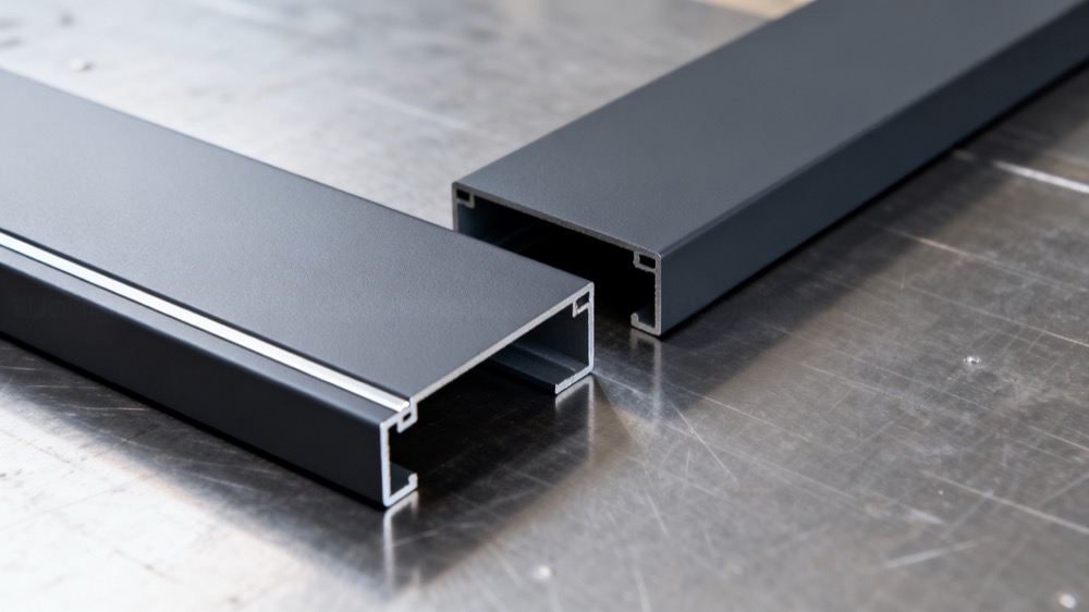
An exposed corner can attract powder during electrostatic spraying and still have a thin film after cure. As the powder melts and flows, the coating may pull back from a sharp corner. The result can be a narrow strip of low film build along the apex even when both adjoining faces look well coated.
Inspect the same feature before and after cure. A visibly sparse powder layer before cure points toward deposition or physical access. A corner that appears covered before cure but measures thin afterward warrants a closer look at edge geometry and coating flow. Visual inspection of uncured powder is a useful clue, not a substitute for measuring the cured film.
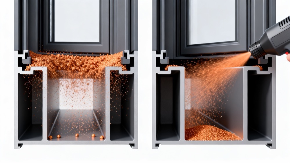
Glazing pockets, gasket grooves, and deep returns can be difficult to coat because the electrostatic field concentrates near the opening. Charged powder tends to collect on the lips and nearby faces rather than reach the bottom. This is commonly called the Faraday cage effect.
Airflow can make the pattern worse. Too little delivery air may fail to carry powder into the recess; too much can disturb deposited powder or create turbulence. If the lips are already heavy and the root is still thin, raising voltage or increasing powder output indiscriminately can make the imbalance more pronounced.
Check when the bare area first appeared. A saw cut made after coating exposes a new aluminum surface. A bare patch that matches the hanger contact is a rack mark. A recurring strip behind a flange may be a spray shadow caused by profile orientation or limited gun access. Mark these separately on the inspection drawing so operators do not spend time correcting defects that gun settings cannot resolve.
| Where the defect appears | What to investigate first | Useful next check |
|---|---|---|
| Narrow line along an exposed corner | Sharp radius, burrs, or film pullback | Compare before and after cure; section the corner if needed |
| Heavy channel lips and a thin root | Electrostatic shielding or poor powder delivery | Try a dedicated recess pass and measure the root |
| Thin strip behind a flange | Racking angle or gun access | Reorient a trial part and compare the same locations |
| Patch matching a hook contact | Rack contact location | Check whether the contact can move to an approved hidden area |
| Bare metal on a post-coating cut | Fabrication sequence | Confirm how the assembled design protects or accepts the cut face |
Start with the electrical path from the aluminum through the hook and rack to ground. Cured powder buildup at contact points can make grounding inconsistent. Check the complete path using the line's approved procedure and equipment requirements. If coverage changes from rack to rack under the same gun recipe, investigate contact quality before editing the recipe.
Then look at how the extrusion hangs. Can the spray reach the pocket from a useful angle? Does an adjacent profile block the opening? Trial a different orientation or spacing on a small load. The aim is to expose the difficult feature without introducing new contact marks or reducing production capacity unnecessarily.
Test a dedicated first pass for the groove or pocket. Aim the powder stream into the opening rather than across it. On a corona gun, trial lower voltage or a lower current limit within the equipment manufacturer's operating guidance. Adjust delivery air separately so you can see whether electrical settings or airflow made the difference.
Finish with the normal face pass. Measure the channel root and the lips, not just the outer face. A successful change raises film build at the root without creating ridges, visible texture changes, or excessive thickness where a gasket must seat. Record gun angle, distance, and line speed together with the settings; the same voltage can produce different results when the geometry changes.
Where the extrusion design and tolerances permit, ask engineering to review the edge radius and any burrs left by cutting or machining. Do not round a seal seat, drainage feature, or mating surface without approval. If the geometry cannot change, compare candidate powders on the actual profile. Ask the supplier for evidence of cured edge coverage, not just a recommended thickness for flat surfaces.
Confirm cure against the powder's technical data sheet using part metal temperature and the specified time at temperature. Oven air temperature alone does not establish that the profile received the required cure. Also keep pretreatment checks separate: a thicker film does not correct poor cleaning, an out-of-control pretreatment process, or inadequate cure.
Measure dry film thickness after cure with an eddy-current gauge suitable for nonconductive coatings on aluminum. Verify the gauge and follow its adjustment procedure on representative uncoated material. A probe that gives reliable readings on a broad face may not give reliable readings at a sharp apex or inside a narrow groove. Check the probe's limits for edge distance, curvature, and access before treating the number as an acceptance result.
Mark the exterior face, shoulder near the exposed edge, channel lip, channel root, and any service-critical return on a cross-section drawing. Give each point an identifier. Sample high-risk locations along the extrusion and across rack positions. This helps distinguish a consistent geometry problem from a rack-position effect or a change near the ends of a long profile.
When a probe cannot measure the true apex reliably, use an agreed destructive method, such as a prepared cross-section examined under a calibrated microscope. Report a near-edge gauge reading as a near-edge reading; it does not establish the thickness at the apex.
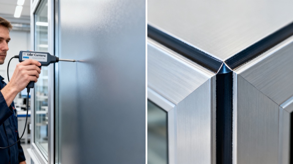
Architectural coating specifications define where standard appearance and thickness checks apply. Under the QUALICOAT specification, edges, deep recesses, and secondary surfaces are excluded from the standard definition of the significant surface. A passing thickness result on the visible face therefore does not demonstrate that every channel or corner meets a project-specific coverage requirement.
If a pocket, return, or exposed edge needs its own minimum, put the location, test method, and acceptance criteria on the drawing or purchase specification. Also identify concealed or post-machined areas where full coverage is not required. That distinction prevents a perfectly acceptable face inspection from being mistaken for approval of the entire cross-section.
Consider an illustrative case: the exterior face of a window profile meets its film-build target, but a glazing pocket has a thin root and heavy lips. The following trial is a troubleshooting example, not a report of Yinda production results.
1. Establish the baseline. With the current recipe, record cured readings at the face, lips, and channel root using suitable methods. Photograph each location.
2. Check the rack. Verify grounding and trial an orientation that exposes the channel more directly. Keep the powder, line speed, and cure schedule unchanged.
3. Change one application variable at a time. Compare the baseline with a targeted recess-first pass. If the root remains low, compare lower electrostatic output or revised airflow in separate runs.
4. Check assembly as well as film build. Confirm that the root improves, the visible face still meets its appearance requirements, and the added film does not interfere with the gasket or glazing bead.
5. Repeat under normal loading. Approve the recipe only after the improvement holds across relevant rack positions. Record the accepted setup and inspection points for the next run.
The key comparison is the channel root before and after the change. A higher average across the whole profile could simply mean that the easy surfaces got thicker.
Send Yinda Technology your extrusion drawing, photos of the thin spots, and the project's finish specification. If available, include the current powder, gun settings, rack orientation, cure schedule, and thickness readings by location. We can use that information to discuss powder selection and define a practical profile trial, so you can assess coverage on the areas that matter before committing to a production run.
Not necessarily. In a recessed channel, higher voltage can favor deposition at the opening while leaving the root thin. Check grounding first, then compare a controlled lower-output recess pass against the baseline. An exposed corner that loses film during cure needs a different investigation.
Use the project specification, the applicable architectural coating requirements, and the powder supplier's technical data sheet. Do not assume a standard face-thickness target automatically applies to a corner apex or groove root. Specify critical locations and how to measure them before releasing production.
Sometimes, but only after identifying why the first coat was thin. A second pass can repeat the same spray shadow or create excess film on the lips. Confirm that the proposed recoat is permitted for the coating system and that the finished profile still meets appearance and fit requirements.
No. A flat panel is useful for checking properties such as appearance and flat-surface thickness, but it does not reproduce an extrusion's sharp corners, recess depth, or spray shadows. Qualify critical features on a representative production profile.
A different powder may improve how much film a sharp edge retains after cure. It will not fix an electrically isolated rack or create spray access behind a flange. Compare candidate powders using the same extrusion and documented application conditions rather than comparing flat panels alone.
Inspect the uncured deposit and compare it with the cured film at the same feature on representative trial pieces. Sparse deposit before cure suggests an application problem. A well-covered uncured corner that becomes thin after cure merits a geometry and formulation review. Confirm uncertain results with a cross-section.
1. QUALICOAT, *QUALICOAT Specifications*, §2.1 "Appearance" and §2.3 "Coating Thickness." Covers significant surfaces, inspection locations, and thickness requirements for architectural aluminum. [View the specification PDF]. [qualisino]
2. Powder Coating Institute, *Frequently Asked Questions*, grounding and Faraday-area coverage guidance. Explains the interaction between powder charge, airflow, and electric-field control. [Read the technical FAQ]. [powdercoating]
3. DeFelsko, *How to Measure Powder Coating Thickness on Steel, Aluminum, or Wood*. Describes eddy-current measurement on aluminum and distinguishes uncured powder measurement from cured film measurement. [Read the measurement guide]. [defelsko]
4. DeFelsko, *How to Measure Coating and Paint Thickness with the PosiTector 6000*. Covers gauge calibration, verification, adjustment, and measurement. [View the gauge guide]. [defelsko]
5. *Powder Coated Tough*, *The Shortest Path to the Ground*. Discusses the effect of rack and hook contact on electrostatic application consistency. [Read the grounding article]. [powdercoatedtough]
6. Powder-X, *Faraday Cage Effect in Powder Coating: Causes & Fixes*. Provides practical guidance on recess-first application, voltage and current, airflow, and spray angle. [Read the troubleshooting article]. [blog.powderx]


